Principles of Optical Fiber Communications
The digital communication techniques discussed so far have led to the advancement in the study of both Optical and Satellite communications. Let us take a look at them.
Fiber Optics
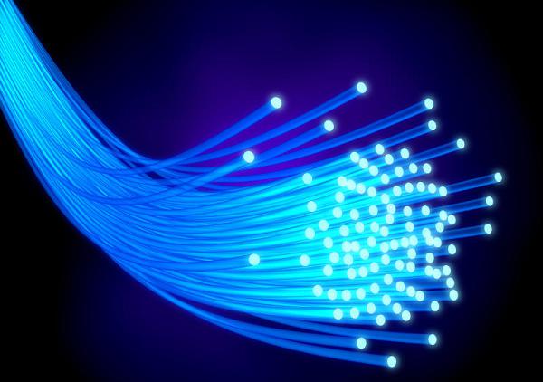
An optical fiber can be understood as a dielectric waveguide, which operates at optical frequencies. The device or a tube, if bent or if terminated to radiate energy, is called a waveguide, in general. Following image depicts a bunch of fiber optic cables.

The electromagnetic energy travels through it in the form of light. The light propagation, along a waveguide can be described in terms of a set of guided electromagnetic waves, called as modes of the waveguide.
Working Principle
A fundamental optical parameter one should have an idea about, while studying fiber optics is Refractive index. By definition, “The ratio of the speed of light in a vacuum to that in matter is the index of refraction n of the material.” It is represented as −
$$n = \frac{c}{v}$$
Where,
c = the speed of light in free space = 3 × 10⁸ m/s
v = the speed of light in di-electric or non-conducting material
Generally, for a travelling light ray, reflection takes place when n2 < n1 . The bent of light ray at the interface is the result of difference in the speed of light in two materials that have different refractive indices. The relationship between these angles at the interface can be termed as Snell’s law. It is represented as −
$$n_1sin\phi _1 = n_2sin\phi _2$$
Where,
$\phi _1$ is the angle of incidence
$\phi _2$ is the refracted angle
n1 and n2 are the refractive indices of two materials
For an optically dense material, if the reflection takes place within the same material, then such a phenomenon is called as internal reflection. The incident angle and refracted angle are shown in the following figure.

If the angle of incidence $\phi _1$ is much larger, then the refracted angle $\phi _2$ at a point becomes Π/2 . Further refraction is not possible beyond this point. Hence, such a point is called as Critical angle $\phi _c$. When the incident angle $\phi _1$ is greater than the critical angle, the condition for total internal reflection is satisfied.
The following figure shows these terms clearly.

A light ray, if passed into a glass, at such condition, it is totally reflected back into the glass with no light escaping from the surface of the glass.
Parts of a Fiber
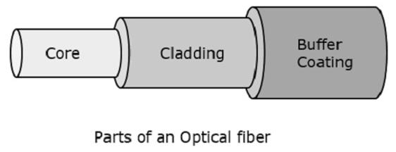
The most commonly used optical fiber is single solid di-electric cylinder of radius a and index of refraction n1. The following figure explains the parts of an optical fiber.

This cylinder is known as the Core of the fiber. A solid di-electric material surrounds the core, which is called as Cladding. Cladding has a refractive index n2 which is less than n1.
Cladding helps in −
- Reducing scattering losses.
- Adds mechanical strength to the fiber.
- Protects the core from absorbing unwanted surface contaminants.
Types of Optical Fibers
Depending upon the material composition of the core, there are two types of fibers used commonly. They are −
Step-index fiber − The refractive index of the core is uniform throughout and undergoes an abrupt change (or step) at the cladding boundary.
Graded-index fiber − The core refractive index is made to vary as a function of the radial distance from the center of the fiber.
Both of these are further divided into −
Optical Fiber Communications
The communication system of fiber optics is well understood by studying the parts and sections of it. The major elements of an optical fiber communication system are shown in the following figure.

The basic components are light signal transmitter, the optical fiber, and the photo detecting receiver. The additional elements such as fiber and cable splicers and connectors, regenerators, beam splitters, and optical amplifiers are employed to improve the performance of the communication system.
Functional Advantages
The functional advantages of optical fibers are −
The transmission bandwidth of the fiber optic cables is higher than the metal cables.
The amount of data transmission is higher in fiber optic cables.
The power loss is very low and hence helpful in long-distance transmissions.
Fiber optic cables provide high security and cannot be tapped.
Fiber optic cables are the most secure way for data transmission.
Fiber optic cables are immune to electromagnetic interference.
These are not affected by electrical noise.
Physical Advantages
The physical advantages of fiber optic cables are −
The capacity of these cables is much higher than copper wire cables.
Though the capacity is higher, the size of the cable doesn’t increase like it does in copper wire cabling system.
The space occupied by these cables is much less.
The weight of these FOC cables is much lighter than the copper ones.
Since these cables are di-electric, no spark hazards are present.
These cables are more corrosion resistant than copper cables, as they are bent easily and are flexible.
The raw material for the manufacture of fiber optic cables is glass, which is cheaper than copper.
Fiber optic cables last longer than copper cables.
Disadvantages
Although fiber optics offer many advantages, they have the following drawbacks −
Though fiber optic cables last longer, the installation cost is high.
The number of repeaters are to be increased with distance.
They are fragile if not enclosed in a plastic sheath. Hence, more protection is needed than copper ones.
Applications of Fiber Optics
The optical fibers have many applications. Some of them are as follows −
Used in telephone systems
Used in sub-marine cable networks
Used in data link for computer networks, CATV Systems
Used in CCTV surveillance cameras
Used for connecting fire, police, and other emergency services.
Used in hospitals, schools, and traffic management systems.
They have many industrial uses and also used for in heavy duty constructions.


