In Differential Phase Shift Keying (DPSK) the phase of the modulated signal is shifted relative to the previous signal element. No reference signal is considered here. The signal phase follows the high or low state of the previous element. This DPSK technique doesn’t need a reference oscillator.
The following figure represents the model waveform of DPSK.
It is seen from the above figure that, if the data bit is Low i.e., 0, then the phase of the signal is not reversed, but continued as it was. If the data is a High i.e., 1, then the phase of the signal is reversed, as with NRZI, invert on 1 (a form of differential encoding).
If we observe the above waveform, we can say that the High state represents an M in the modulating signal and the Low state represents a W in the modulating signal.
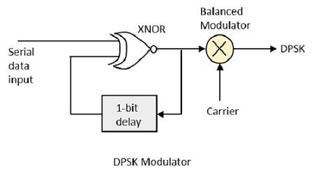
DPSK is a technique of BPSK, in which there is no reference phase signal. Here, the transmitted signal itself can be used as a reference signal. Following is the diagram of DPSK Modulator.
DPSK encodes two distinct signals, i.e., the carrier and the modulating signal with 180° phase shift each. The serial data input is given to the XNOR gate and the output is again fed back to the other input through 1-bit delay. The output of the XNOR gate along with the carrier signal is given to the balance modulator, to produce the DPSK modulated signal.
In DPSK demodulator, the phase of the reversed bit is compared with the phase of the previous bit. Following is the block diagram of DPSK demodulator.
From the above figure, it is evident that the balance modulator is given the DPSK signal along with 1-bit delay input. That signal is made to confine to lower frequencies with the help of LPF. Then it is passed to a shaper circuit, which is a comparator or a Schmitt trigger circuit, to recover the original binary data as the output.