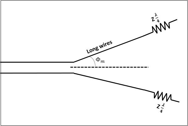
A better version of long-wire antennas is the V-Antenna. This antenna is formed by arranging the long wire in a V-shaped pattern. The end wires are called as legs. This antenna is a bi-directional resonant antenna.
The frequency range of operation of V-antenna is around 3 to 30 MHz. This antenna works in high frequency range.
Two long wires are connected in the shape of V to make a V-antenna. The two long wires are excited with 180˚ out of phase. As the length of these wires increases, the gain and directivity also increases.
The following figure shows a V-antenna with the transmission line impedance z and the lengh of the wire λ/2, making an angle Φm with the axis, which is called as apex angle.
The gain achieved by V-antenna is higher than normal single long wire antenna. The gain in this V-formation is nearly twice compared to the single long wire antenna, which has a length equal to the legs of V-antenna. If wide range of radiation is to be achieved, the apex angle should have an average value between higher and lower frequencies in terms of the number of λ/2 in each leg.
The radiation pattern of a V-antenna is bi-directional. The radiation obtained on each transmission line is added to obtain the resultant radiation pattern. This is well explained in the following figure −
The figure shows the radiation pattern of V-antenna. The two transmission lines forming V-pattern are AA’ and BB’. The patterns of individual transmission lines and the resultant pattern are shown in the figure. The resultant pattern is shown along the axis. This pattern resembles the broad-side array.
If another V-antenna is added to this antenna and fed with 90˚ phase difference, then the resultant pattern would be end-fire, doubling the power gain. The directivity is further increased by adding the array of V-antennas.
The following are the advantages of V-antenna −
The following are the disadvantages of V-antenna −
The following are the applications of V-antenna −